

SECTION 07 95 00
Architecture Intelligence
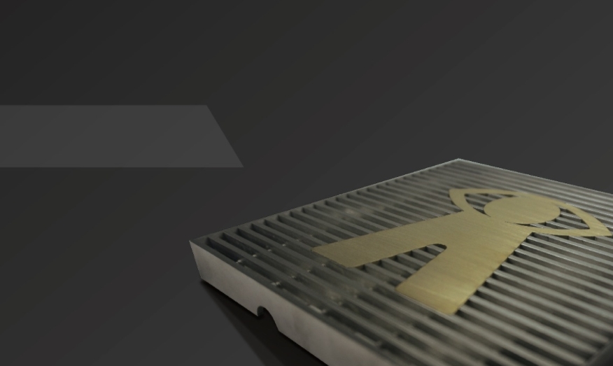
Expansion Joint System
PART 1 - GENERAL
1.01 RELATED DOCUMENTS
Drawings and general provisions of the Contract, including General and Supplementary Conditions and Division 01 Specification Sections, apply to this Section.
3.1 SUMMARY
A. This Section includes the following: Architectural joint systems for building exteriors.
B. Related Sections include the following:
1. Division 03 Section "Cast-in-Place Concrete" for cast-in architectural-joint-system frames furnished, but not installed, in this Section.
2. Division 04 Section "Unit Masonry" for masonry wall joint systems.
3. Division 07 Section "Sheet Metal Roofing" for sheet metal roof joint systems.
4. Division 07 Section "Sheet Metal Flashing and Trim" for sheet metal wall joint systems.
5. Division 07 Section "Fire-Resistive Joint Systems" for liquid-applied joint sealants in fire-resistive building joints.
6. Division 07 Section "Joint Sealants" for liquid-applied joint sealants.
3.2 DEFINITIONS
A. Maximum Joint Width: Widest linear gap a joint system tolerates and in which it performs its designed function without damaging its functional capabilities.
B. Minimum Joint Width: Narrowest linear gap a joint system tolerates and in which it performs its designed function without damaging its functional capabilities.
C. Movement Capability: Value obtained from the difference between widest and narrowest widths of a joint.
D. Nominal Joint Width: The width of the linear opening specified in practice and in which the joint system is installed.
3.3 SUBMITTALS
A. Shop Drawings: Provide the following for each joint system specified and obtain approval prior to fabrication and shipment of materials to the job site:
Placement Drawings: Include line diagrams showing plans, elevations, sections, details, splices, blackout requirement, entire route of each joint system, and attachments to other work. Where joint systems change planes, provide isometric or clearly detailed drawing depicting how components interconnect.
B. Product Data: Submit copies of manufacturer’s latest materials specified herein for approval, and obtain approval before materials are fabricated and delivered to the site. Data to clearly indicate movement capability of cover assemblies and suitability of material used in exterior seal for UV exposure.
A. Samples for Initial Selection:
Include manufacturer's color charts showing the standard range of colors and finishes available for each exposed metal and elastomeric seal material.
B. Certificates – UL 2079 test reports from qualified independent testing laboratory indicating and interpreting test results relative to compliance of fire-rated expansion joint assemblies with requirements indicated.
3.4 QUALITY ASSURANCE
A. Installer Qualifications: Approved by manufacturer and having experience installing joint systems that are similar in design complexity.
B. Source Limitations: Obtain all architectural joint systems through one source from a single manufacturer.
C. Product Options: Drawings indicate size, profiles, and dimensional requirements of architectural joint systems and are based on the specific systems indicated.
Do not modify intended aesthetic effects, as judged solely by Architect, except with Architect's approval. If modifications are proposed, submit comprehensive explanatory data to Architect for review.
D. Loading Characteristics: Standard loading refers to covers that are capable of withstanding up to 500 lb. point loads. Heavy duty refers to covers that are capable of withstanding up to 2000 lb. point loads.
a. Fire-Test-Response Characteristics: Where indicated, provide architectural joint system and fire-barrier assemblies identical to those of assemblies tested for fire resistance per UL 2079 and/or ASTM E 1966 by a testing and inspecting agency acceptable to authorities having jurisdiction. Fire rating not less than the rating of adjacent construction.
b. Manufacturer to provide 5 year warranty for all joint covers.
3.5 COORDINATION
A. Coordinate installation of exterior wall joint systems with roof expansion assemblies to ensure that wall transitions are watertight.
PART 2 - PRODUCTS
2.1 MATERIALS
A. Aluminum: ASTM B 221, Alloy 6063-T5, 6063-T6, 6063-T52, 6061-T5, 6061-T6, 6061- T51, 6105-T5, 6105-T6, 6005-T5, 6005A-T5, 6005A-T61 for extrusions; ASTM B 209,
Alloy 6061-T6, 3003-H14, 5005-H34 for sheet and plate.
1. Apply manufacturer's standard protective coating on aluminum surfaces to be placed in contact with cementitious materials.
2. Mill Finish: AA-M10 (Mechanical Finish: as fabricated, unspecified).
3. Class II, Clear Anodic Finish: AA-M12C22A31 (Mechanical Finish: nonspecular as fabricated; Chemical Finish: etched, medium matte; Anodic Coating: Architectural Class II, clear coating 0.010 mm or thicker) complying with AAMA 611.
4. Class II, Color Anodic Finish: AA-M12C22A32/A34 (Mechanical Finish: nonspecular as fabricated; Chemical Finish: etched, medium matte; Anodic Coating: Architectural Class II, integrally colored or electrolytically deposited color coating 0.010 mm or thicker) complying with AAMA 611.
5. High-Performance Organic Finish (Two-Coat Fluoropolymer): AA-C12C40R1x (Chemical Finish: cleaned with inhibited chemicals; Chemical Finish: conversion coating; Organic Coating: manufacturer's standard two-coat, thermocured system consisting of specially formulated inhibitive primer and fluoropolymer color topcoat containing not less than 70 percent polyvinylidene fluoride resin by weight). Prepare, pretreat, and apply coating to exposed metal surfaces to comply with AAMA 2604 and with coating and resin manufacturers' written instructions.
B. Stainless Steel: ASTM A167, A240A, A240M - Type 304 for plates, sheet, and strips.
Finish: No.4, directional satin.
E. Grind and polish surfaces to produce uniform, directionally textured, polished finish indicated, free of cross scratches. Run grain with long dimension of each piece.
F. When polishing is completed, passivate and rinse surfaces. Remove embedded foreign matter and leave surfaces chemically clean.
C. Brass: ASTM B 36/B 36M, UNS Alloy C26000 for half hard sheet and coil.
D. Bronze: ASTM B 455, Alloy C38500 for extrusions; Alloy C28000 Muntz Metal for plates.
E. Elastomeric Seals: Preformed elastomeric membranes or extrusions to be installed in metal frames.
F. Compression Seals: ASTM D2000; preformed rectangular elastomeric extrusions having internal baffle system and designed to function under compression.
G. Fire Barriers: Any material or material combination, when fire tested after cycling, designated to resist the passage of flame and hot gases through a movement joint and to meet performance criteria for required rating period.
H. Moisture Barrier: 7-ply laminate reinforced Polyethylene.
I. Accessories: Manufacturer's standard anchors, clips, fasteners, set screws, spacers, and other accessories compatible with material in contact, as indicated or required for complete installations.
2.2 DELIVERY; STORAGE HANDELING;
C. Deliver materials to the project site in unopened original factory packaging clearly labeled to show manufacturer: Architecture Intelligence LLC.
D. Store materials in original, undamaged packaging in a clean, dry place out of direct sunlight and exposure to the elements. A minimum room temperature of 4°C (40°F) and a maximum of 38°C (100°F) should be maintained.
E. Materials must be stored flat.
F. Project Conditions
Materials must be acclimated in an environment of 18°-24°C (65°-75°F) for at least 24 hours prior to beginning the installation.
PART 3 - EXECUTION
1.2 EXAMINATION
Examine surfaces and blackouts where architectural joint systems will be installed for installation tolerances and other conditions affecting performance of work.
1.3 PREPARATION
A. Prepare substrates according to architectural joint system manufacturer's written instructions.
B. Repair concrete slabs and blackouts using manufacturer's recommended repair grout of compressive strength adequate for anticipated structural loadings.
C. Coordinate and furnish anchorages, setting drawings, and instructions for installing joint systems. Provide fasteners of metal, type, and size to suit type of construction indicated and to provide for secure attachment of joint systems.
D. Cast-In Frames: Coordinate and furnish frames to be cast into concrete.
1.4 INSTALLATION
A. Comply with manufacturer's written instructions for storing, handling, and installing architectural joint assemblies and materials unless more stringent requirements are indicated.
B. Metal Frames: Perform cutting, drilling, and fitting required to install joint systems.
1. Install in true alignment and proper relationship to joints and adjoining finished surfaces measured from established lines and levels.
2. Adjust for differences between actual structural gap and nominal design gap due to ambient temperature at time of installation. Notify Architect where discrepancies occur that will affect proper joint installation and performance.
3. Cut and fit ends to accommodate thermal expansion and contraction of metal without buckling of frames.
4. Locate in continuous contact with adjacent surfaces.
5. Standard-Duty Systems: Shim to level where required. Support underside of frames continuously to prevent vertical deflection when in service.
6. Heavy-Duty Systems: Repair or grout blackout as required for continuous frame support and to bring frame to proper level. Shimming is not allowed.
7. Locate anchors at interval recommended by manufacturer, but not less than 3 inches
from each end and not more than 24 inches o.c.
C. Seals in Metal Frames: Install elastomeric seals and membranes in frames to comply with manufacturer's written instructions. Install with minimum number of end joints.
1. | Provide in continuous lengths for straight sections. | |
2 | Seal transitions according to manufacturer's written instructions. | Vulcanize or heat- |
3 | weld field-spliced joints as recommended by manufacturer. |
3. Installation: Mechanically lock seals into frames or adhere to frames with adhesive or pressure-sensitive tape as recommended by manufacturer.
D. Compression Seals: Apply adhesive or lubricant adhesive as recommended by manufacturer before installing compression seals.
E. Terminate exposed ends of joint assemblies with field- or factory-fabricated termination devices.
F. Fire-Resistance-Rated Assemblies: Coordinate installation of architectural joint assembly materials and associated work so complete assemblies comply with assembly performance requirements.
Fire Barriers: Install fire barriers to provide continuous, uninterrupted fire resistance throughout length of joint, including transitions and field splices.
G. Water Barrier: Provide water barrier at exterior joints and where called for on Drawings.
Provide drainage fittings where indicated.
1.5 PROTECTION
A. Do not remove protective covering until finish work in adjacent areas is complete. When protective covering is removed, clean exposed metal surfaces to comply with manufacturer's written instructions.
B. Protect the installation from damage by work of other Sections. Where necessary due to heavy construction traffic, remove and properly store cover plates or seals and install temporary protection over joints. Reinstall cover plates or seals prior to Substantial Completion of the Work.
END OF SECTION 07